

Valve proving system VDK 200 A S02 H2 Dungs
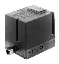
- These valve proving systems VDK 200 A S02 H2 may be used with any other valve whose tightness in counter-flow direction excludes by construction a leakage in flow direction.
- Equipment independent of residual pressure.
- Test volume ≤ 1 l
- The complete test procedure is defined.
- Short release time: approximately 10 seconds.
- Tightness or leaks are displayed by a LED.
- External fault display.
- Suitable for TRD systems.
- The VDK 200 A S02 H2 is suitable for all Dungs valves according to EN 161 Class A.
- Suitable for hydrogen.
Technical specifications VDK 200 A S02 H2
| Type valve proving system | Code | Voltage (V) | Frequency (Hz) | pmax (mbar) | Ambient temperature (oC) | Max. number of test cycles | Release time(sec) | Degree of protection |
|---|---|---|---|---|---|---|---|---|
| VDK 200 A S02 H2 | 214445 | 230 | 50 | 40 | -10÷60 | 15/h | aprox. 10 | IP 40 |
| VDK 200 A S02 H2 | 222747 | 120 | 60 |
Dimensions valve proving system (mm)
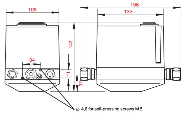
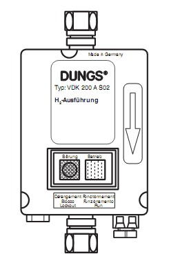
For the images that aren't clear move the mouse over them to zoom.
VDK 200 Function principle
VDK 200 A S02 H2 operates according to the pressure build-up principle. The program module starts to function when heat is requested.
Test is performed depending on the burner functional procedure:
- Test prior to burner start or
- Test during pre-purge time or
- Test after burner shut-down.
The VDK performs a self-test during a switching sequence.
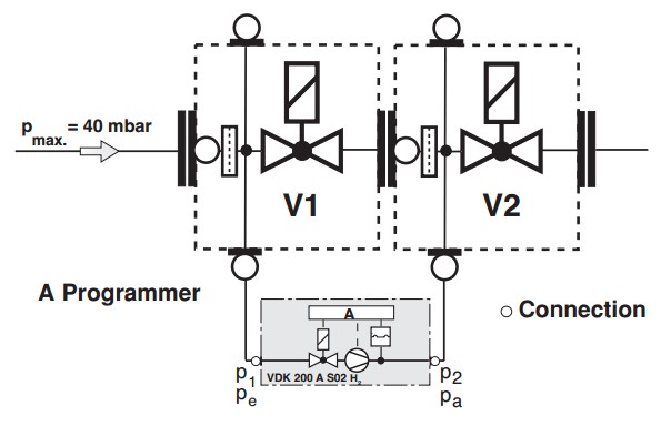
Program flowchart VDK 200
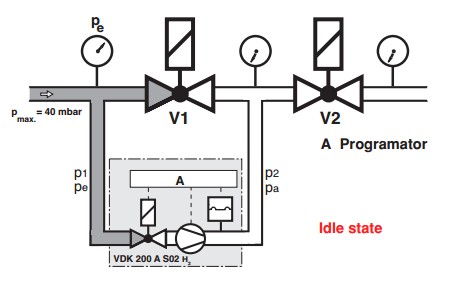
- In starea neactivata ventilele V1 si V2 sunt inchise.
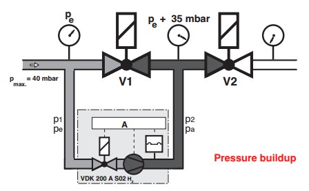
- Pressure build-up: The internal motor pump raises gas pressure in the test section by approx. 35 mbar compared to the pressure applied to the inlet section of valve V1. During the test period (pump period), the integrated differential pressure switch monitors the test section for leaks. When the test pressure is reached, the motor pump switches off (end of test period). The release time (approx. 10 s) is independent on test volume (max. 1 liter) and inlet pressure (max. 40 mbar). If the test section is leak-tight, the contact is released to the automatic burner control after (approx. 10 s) and the yellow LED comes on. If the test section is leaky or if the pressure rise by +35 mbar is not reached during the test period (max. 5 s), the VDK 200 A S02 H2 after 32 ± 3 s switches to fault. The red signla lamp lights as long as the contact is released by the regulator or thermostat (heat request).
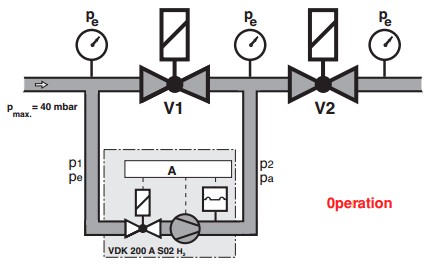
- Operation: Valves V1 and V2 are open, the internal valve of VDK 200 A S02 H2 is closed.
Prices
| Code | Type | Prices without VAT |
|---|---|---|
| 214445 | Valve proving system VDK 200 A S02 H2 | 0.00 |
| 222747 | Valve proving system VDK 200 A S02 H2 | 0.00 |
In case the price is missing or for a list of discounts contact
us directly to receive an offer.